Loading Dan’s ratings…
← All modelsAcoustics / 5 versions
Acoustic horn array
Experimental two-piece microphone horns, base rings and a segmented hemispherical chassis.
AH-007
Latest · Prototype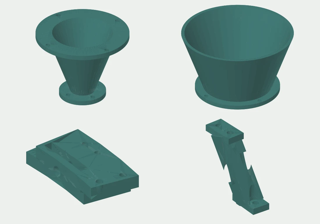
Segmented hoops, ribs, flanged horns, wiring saddles and an equipment bay for the 157-horn hemisphere.
Download version ZIP 4.6 MB156 individual print & CAD files
- Rib 1, interval 1; two M5 bolts at each foot · quantity 1STL · 135 KB · Print geometry
- Rib 2, interval 1; two M5 bolts at each foot · quantity 1STL · 124 KB · Print geometry
- Rib 3, interval 1; two M5 bolts at each foot · quantity 1STL · 132 KB · Print geometry
- Rib 4, interval 1; two M5 bolts at each foot · quantity 1STL · 113 KB · Print geometry
- Rib 5, interval 1; two M5 bolts at each foot · quantity 1STL · 113 KB · Print geometry
- Rib 6, interval 1; two M5 bolts at each foot · quantity 1STL · 132 KB · Print geometry
- Rib 7, interval 1; two M5 bolts at each foot · quantity 1STL · 124 KB · Print geometry
- Rib 1, interval 2; two M5 bolts at each foot · quantity 1STL · 130 KB · Print geometry
- Rib 2, interval 2; two M5 bolts at each foot · quantity 1STL · 119 KB · Print geometry
- Rib 3, interval 2; two M5 bolts at each foot · quantity 1STL · 119 KB · Print geometry
- Rib 4, interval 2; two M5 bolts at each foot · quantity 1STL · 108 KB · Print geometry
- Rib 5, interval 2; two M5 bolts at each foot · quantity 1STL · 108 KB · Print geometry
- Rib 6, interval 2; two M5 bolts at each foot · quantity 1STL · 119 KB · Print geometry
- Rib 7, interval 2; two M5 bolts at each foot · quantity 1STL · 118 KB · Print geometry
- Rib 1, interval 3; two M5 bolts at each foot · quantity 1STL · 118 KB · Print geometry
- Rib 2, interval 3; two M5 bolts at each foot · quantity 1STL · 114 KB · Print geometry
- Rib 3, interval 3; two M5 bolts at each foot · quantity 1STL · 119 KB · Print geometry
- Rib 4, interval 3; two M5 bolts at each foot · quantity 1STL · 109 KB · Print geometry
- Rib 5, interval 3; two M5 bolts at each foot · quantity 1STL · 110 KB · Print geometry
- Rib 6, interval 3; two M5 bolts at each foot · quantity 1STL · 118 KB · Print geometry
- Rib 7, interval 3; two M5 bolts at each foot · quantity 1STL · 113 KB · Print geometry
- Rib 1, interval 4; two M5 bolts at each foot · quantity 1STL · 109 KB · Print geometry
- Rib 2, interval 4; two M5 bolts at each foot · quantity 1STL · 109 KB · Print geometry
- Rib 3, interval 4; two M5 bolts at each foot · quantity 1STL · 109 KB · Print geometry
- Rib 4, interval 4; two M5 bolts at each foot · quantity 1STL · 110 KB · Print geometry
- Rib 5, interval 4; two M5 bolts at each foot · quantity 1STL · 111 KB · Print geometry
- Rib 6, interval 4; two M5 bolts at each foot · quantity 1STL · 109 KB · Print geometry
- Rib 7, interval 4; two M5 bolts at each foot · quantity 1STL · 108 KB · Print geometry
- Rib 1, interval 5; two M5 bolts at each foot · quantity 1STL · 97 KB · Print geometry
- Rib 2, interval 5; two M5 bolts at each foot · quantity 1STL · 103 KB · Print geometry
- Rib 3, interval 5; two M5 bolts at each foot · quantity 1STL · 114 KB · Print geometry
- Rib 4, interval 5; two M5 bolts at each foot · quantity 1STL · 102 KB · Print geometry
- Rib 5, interval 5; two M5 bolts at each foot · quantity 1STL · 99 KB · Print geometry
- Rib 6, interval 5; two M5 bolts at each foot · quantity 1STL · 96 KB · Print geometry
- Rib 7, interval 5; two M5 bolts at each foot · quantity 1STL · 101 KB · Print geometry
- Rib 1, interval 6; two M5 bolts at each foot · quantity 1STL · 92 KB · Print geometry
- Rib 2, interval 6; two M5 bolts at each foot · quantity 1STL · 92 KB · Print geometry
- Rib 3, interval 6; two M5 bolts at each foot · quantity 1STL · 90 KB · Print geometry
- Rib 4, interval 6; two M5 bolts at each foot · quantity 1STL · 91 KB · Print geometry
- Rib 5, interval 6; two M5 bolts at each foot · quantity 1STL · 91 KB · Print geometry
- Rib 6, interval 6; two M5 bolts at each foot · quantity 1STL · 93 KB · Print geometry
- Rib 7, interval 6; two M5 bolts at each foot · quantity 1STL · 92 KB · Print geometry
- Crown spider and raised removable horn seat · quantity 1STL · 359 KB · Print geometry
- Floor or roof quadrant; M5 edge grid, M8 tie-rod holes and M20 gland port · quantity 8STL · 416 KB · Print geometry
- Ventilated side half-panel; removable with edge splice plates · quantity 16STL · 378 KB · Print geometry
- M5 two-hole panel splice; 20 mm hole pitch · quantity 48STL · 34 KB · Print geometry
- 87 mm square post module; keyed coupler and continuous M8 steel tie rod · quantity 16STL · 34 KB · Print geometry
- 48 mm keyed post coupler; M8 axial bore, 0.3 mm socket clearance per side · quantity 12STL · 17 KB · Print geometry
- 6 mm panel-to-post spacer; M4 screw and post insert · quantity 32STL · 33 KB · Print geometry
- Horn stalk ring 1; 11 mm cable bore; M3 horn flange, M4 base · quantity 32STL · 188 KB · Print geometry
- Horn stalk ring 2; 11 mm cable bore; M3 horn flange, M4 base · quantity 31STL · 191 KB · Print geometry
- Horn stalk ring 3; 11 mm cable bore; M3 horn flange, M4 base · quantity 28STL · 191 KB · Print geometry
- Horn stalk ring 4; 11 mm cable bore; M3 horn flange, M4 base · quantity 24STL · 203 KB · Print geometry
- Horn stalk ring 5; 11 mm cable bore; M3 horn flange, M4 base · quantity 20STL · 227 KB · Print geometry
- Horn stalk ring 6; 11 mm cable bore; M3 horn flange, M4 base · quantity 14STL · 233 KB · Print geometry
- Horn stalk ring 7; 11 mm cable bore; M3 horn flange, M4 base · quantity 7STL · 199 KB · Print geometry
- Horn stalk ring 8; 11 mm cable bore; M3 horn flange, M4 base · quantity 1STL · 252 KB · Print geometry
- Gusseted base-ring outrigger to bay corner; M5 through fixings · quantity 1STL · 82 KB · Print geometry
- Gusseted base-ring outrigger to bay corner; M5 through fixings · quantity 1STL · 82 KB · Print geometry
- Gusseted base-ring outrigger to bay corner; M5 through fixings · quantity 1STL · 82 KB · Print geometry
- Gusseted base-ring outrigger to bay corner; M5 through fixings · quantity 1STL · 81 KB · Print geometry
- Rear horn section with serviceable M3 flanges · quantity 157STL · 260 KB · Print geometry
- Front horn section with serviceable M3 flanges · quantity 157STL · 153 KB · Print geometry
- Ring 1 keyed half-lap sector; M5 seam bolts, M4 horn mount · quantity 32STL · 147 KB · Print geometry
- Ring 2 keyed half-lap sector; M5 seam bolts, M4 horn mount · quantity 31STL · 149 KB · Print geometry
- Ring 3 keyed half-lap sector; M5 seam bolts, M4 horn mount · quantity 28STL · 140 KB · Print geometry
- Ring 4 keyed half-lap sector; M5 seam bolts, M4 horn mount · quantity 24STL · 135 KB · Print geometry
- Ring 5 keyed half-lap sector; M5 seam bolts, M4 horn mount · quantity 20STL · 126 KB · Print geometry
- Ring 6 keyed half-lap sector; M5 seam bolts, M4 horn mount · quantity 14STL · 127 KB · Print geometry
- Ring 7 keyed half-lap sector; M5 seam bolts, M4 horn mount · quantity 7STL · 128 KB · Print geometry
- ADC board tray; reserved board 70 x 100 x 18 mm; slotted restraint · quantity 20STL · 7 KB · Print geometry
- Ribbed computer/power tray; strap slots, isolated standoffs required · quantity 4STL · 19 KB · Print geometry
- 90 mm rack strip; M4 grid; pair with angle brackets and match-drilled tray walls · quantity 24STL · 133 KB · Print geometry
- 78 mm upper rack strip; continuous M4 steel rods secure the stack · quantity 8STL · 128 KB · Print geometry
- M4 tray-to-rack angle; transfer drill horizontal rack hole to suit board stack · quantity 52STL · 34 KB · Print geometry
- Removable battery shelf; 180 x 160 x 80 mm pack reserve and straps · quantity 1STL · 152 KB · Print geometry
- Battery shelf extension to rack; M4 attachment · quantity 4STL · 50 KB · Print geometry
- 16 mm open cable saddle; hook-and-loop tie; shares inner ring-seam M5 bolt · quantity 49STL · 18 KB · Print geometry
- Rib 1, interval 1; two M5 bolts at each foot · quantity 1STEP · 156 KB · Editable CAD
- Rib 2, interval 1; two M5 bolts at each foot · quantity 1STEP · 146 KB · Editable CAD
- Rib 3, interval 1; two M5 bolts at each foot · quantity 1STEP · 151 KB · Editable CAD
- Rib 4, interval 1; two M5 bolts at each foot · quantity 1STEP · 154 KB · Editable CAD
- Rib 5, interval 1; two M5 bolts at each foot · quantity 1STEP · 153 KB · Editable CAD
- Rib 6, interval 1; two M5 bolts at each foot · quantity 1STEP · 151 KB · Editable CAD
- Rib 7, interval 1; two M5 bolts at each foot · quantity 1STEP · 147 KB · Editable CAD
- Rib 1, interval 2; two M5 bolts at each foot · quantity 1STEP · 144 KB · Editable CAD
- Rib 2, interval 2; two M5 bolts at each foot · quantity 1STEP · 126 KB · Editable CAD
- Rib 3, interval 2; two M5 bolts at each foot · quantity 1STEP · 151 KB · Editable CAD
- Rib 4, interval 2; two M5 bolts at each foot · quantity 1STEP · 126 KB · Editable CAD
- Rib 5, interval 2; two M5 bolts at each foot · quantity 1STEP · 127 KB · Editable CAD
- Rib 6, interval 2; two M5 bolts at each foot · quantity 1STEP · 153 KB · Editable CAD
- Rib 7, interval 2; two M5 bolts at each foot · quantity 1STEP · 126 KB · Editable CAD
- Rib 1, interval 3; two M5 bolts at each foot · quantity 1STEP · 138 KB · Editable CAD
- Rib 2, interval 3; two M5 bolts at each foot · quantity 1STEP · 120 KB · Editable CAD
- Rib 3, interval 3; two M5 bolts at each foot · quantity 1STEP · 146 KB · Editable CAD
- Rib 4, interval 3; two M5 bolts at each foot · quantity 1STEP · 129 KB · Editable CAD
- Rib 5, interval 3; two M5 bolts at each foot · quantity 1STEP · 130 KB · Editable CAD
- Rib 6, interval 3; two M5 bolts at each foot · quantity 1STEP · 146 KB · Editable CAD
- Rib 7, interval 3; two M5 bolts at each foot · quantity 1STEP · 121 KB · Editable CAD
- Rib 1, interval 4; two M5 bolts at each foot · quantity 1STEP · 125 KB · Editable CAD
- Rib 2, interval 4; two M5 bolts at each foot · quantity 1STEP · 122 KB · Editable CAD
- Rib 3, interval 4; two M5 bolts at each foot · quantity 1STEP · 128 KB · Editable CAD
- Rib 4, interval 4; two M5 bolts at each foot · quantity 1STEP · 114 KB · Editable CAD
- Rib 5, interval 4; two M5 bolts at each foot · quantity 1STEP · 114 KB · Editable CAD
- Rib 6, interval 4; two M5 bolts at each foot · quantity 1STEP · 128 KB · Editable CAD
- Rib 7, interval 4; two M5 bolts at each foot · quantity 1STEP · 122 KB · Editable CAD
- Rib 1, interval 5; two M5 bolts at each foot · quantity 1STEP · 117 KB · Editable CAD
- Rib 2, interval 5; two M5 bolts at each foot · quantity 1STEP · 129 KB · Editable CAD
- Rib 3, interval 5; two M5 bolts at each foot · quantity 1STEP · 126 KB · Editable CAD
- Rib 4, interval 5; two M5 bolts at each foot · quantity 1STEP · 119 KB · Editable CAD
- Rib 5, interval 5; two M5 bolts at each foot · quantity 1STEP · 116 KB · Editable CAD
- Rib 6, interval 5; two M5 bolts at each foot · quantity 1STEP · 114 KB · Editable CAD
- Rib 7, interval 5; two M5 bolts at each foot · quantity 1STEP · 129 KB · Editable CAD
- Rib 1, interval 6; two M5 bolts at each foot · quantity 1STEP · 109 KB · Editable CAD
- Rib 2, interval 6; two M5 bolts at each foot · quantity 1STEP · 111 KB · Editable CAD
- Rib 3, interval 6; two M5 bolts at each foot · quantity 1STEP · 101 KB · Editable CAD
- Rib 4, interval 6; two M5 bolts at each foot · quantity 1STEP · 110 KB · Editable CAD
- Rib 5, interval 6; two M5 bolts at each foot · quantity 1STEP · 101 KB · Editable CAD
- Rib 6, interval 6; two M5 bolts at each foot · quantity 1STEP · 110 KB · Editable CAD
- Rib 7, interval 6; two M5 bolts at each foot · quantity 1STEP · 111 KB · Editable CAD
- Crown spider and raised removable horn seat · quantity 1STEP · 451 KB · Editable CAD
- Floor or roof quadrant; M5 edge grid, M8 tie-rod holes and M20 gland port · quantity 8STEP · 107 KB · Editable CAD
- Ventilated side half-panel; removable with edge splice plates · quantity 16STEP · 262 KB · Editable CAD
- M5 two-hole panel splice; 20 mm hole pitch · quantity 48STEP · 22 KB · Editable CAD
- 87 mm square post module; keyed coupler and continuous M8 steel tie rod · quantity 16STEP · 37 KB · Editable CAD
- 48 mm keyed post coupler; M8 axial bore, 0.3 mm socket clearance per side · quantity 12STEP · 19 KB · Editable CAD
- 6 mm panel-to-post spacer; M4 screw and post insert · quantity 32STEP · 9 KB · Editable CAD
- Horn stalk ring 1; 11 mm cable bore; M3 horn flange, M4 base · quantity 32STEP · 173 KB · Editable CAD
- Horn stalk ring 2; 11 mm cable bore; M3 horn flange, M4 base · quantity 31STEP · 180 KB · Editable CAD
- Horn stalk ring 3; 11 mm cable bore; M3 horn flange, M4 base · quantity 28STEP · 209 KB · Editable CAD
- Horn stalk ring 4; 11 mm cable bore; M3 horn flange, M4 base · quantity 24STEP · 175 KB · Editable CAD
- Horn stalk ring 5; 11 mm cable bore; M3 horn flange, M4 base · quantity 20STEP · 270 KB · Editable CAD
- Horn stalk ring 6; 11 mm cable bore; M3 horn flange, M4 base · quantity 14STEP · 273 KB · Editable CAD
- Horn stalk ring 7; 11 mm cable bore; M3 horn flange, M4 base · quantity 7STEP · 214 KB · Editable CAD
- Horn stalk ring 8; 11 mm cable bore; M3 horn flange, M4 base · quantity 1STEP · 152 KB · Editable CAD
- Gusseted base-ring outrigger to bay corner; M5 through fixings · quantity 1STEP · 121 KB · Editable CAD
- Gusseted base-ring outrigger to bay corner; M5 through fixings · quantity 1STEP · 118 KB · Editable CAD
- Gusseted base-ring outrigger to bay corner; M5 through fixings · quantity 1STEP · 119 KB · Editable CAD
- Gusseted base-ring outrigger to bay corner; M5 through fixings · quantity 1STEP · 122 KB · Editable CAD
- Rear horn section with serviceable M3 flanges · quantity 157STEP · 49 KB · Editable CAD
- Front horn section with serviceable M3 flanges · quantity 157STEP · 27 KB · Editable CAD
- Ring 1 keyed half-lap sector; M5 seam bolts, M4 horn mount · quantity 32STEP · 153 KB · Editable CAD
- Ring 2 keyed half-lap sector; M5 seam bolts, M4 horn mount · quantity 31STEP · 163 KB · Editable CAD
- Ring 3 keyed half-lap sector; M5 seam bolts, M4 horn mount · quantity 28STEP · 187 KB · Editable CAD
- Ring 4 keyed half-lap sector; M5 seam bolts, M4 horn mount · quantity 24STEP · 131 KB · Editable CAD
- Ring 5 keyed half-lap sector; M5 seam bolts, M4 horn mount · quantity 20STEP · 105 KB · Editable CAD
- Ring 6 keyed half-lap sector; M5 seam bolts, M4 horn mount · quantity 14STEP · 97 KB · Editable CAD
- Ring 7 keyed half-lap sector; M5 seam bolts, M4 horn mount · quantity 7STEP · 80 KB · Editable CAD
- ADC board tray; reserved board 70 x 100 x 18 mm; slotted restraint · quantity 20STEP · 110 KB · Editable CAD
- Ribbed computer/power tray; strap slots, isolated standoffs required · quantity 4STEP · 277 KB · Editable CAD
- 90 mm rack strip; M4 grid; pair with angle brackets and match-drilled tray walls · quantity 24STEP · 43 KB · Editable CAD
- 78 mm upper rack strip; continuous M4 steel rods secure the stack · quantity 8STEP · 47 KB · Editable CAD
- M4 tray-to-rack angle; transfer drill horizontal rack hole to suit board stack · quantity 52STEP · 29 KB · Editable CAD
- Removable battery shelf; 180 x 160 x 80 mm pack reserve and straps · quantity 1STEP · 307 KB · Editable CAD
- Battery shelf extension to rack; M4 attachment · quantity 4STEP · 26 KB · Editable CAD
- 16 mm open cable saddle; hook-and-loop tie; shares inner ring-seam M5 bolt · quantity 49STEP · 38 KB · Editable CAD
AH-004
Prototype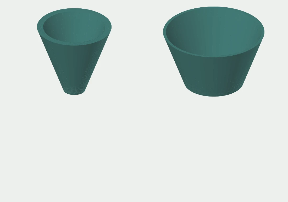
Surface-normal two-piece horns for the 121-horn upper array.
Download version ZIP 74 KB4 individual print & CAD files
- AH 004 P01 rear hornSTL · 178 KB · Print geometry
- AH 004 P01 rear hornSTEP · 13 KB · Editable CAD
- AH 004 P02 front hornSTL · 117 KB · Print geometry
- AH 004 P02 front hornSTEP · 9 KB · Editable CAD
AH-003
Prototype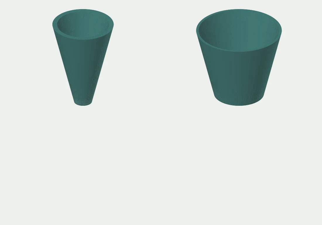
A3 two-piece horn cartridges for the 77-horn bell exploration.
Download version ZIP 84 KB4 individual print & CAD files
- AH 003 P01 rear hornSTL · 203 KB · Print geometry
- AH 003 P01 rear hornSTEP · 13 KB · Editable CAD
- AH 003 P02 front hornSTL · 135 KB · Print geometry
- AH 003 P02 front hornSTEP · 9 KB · Editable CAD
AH-002
Prototype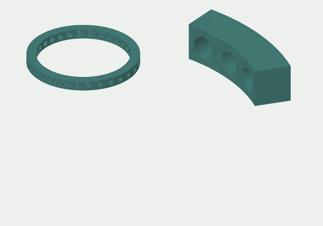
Central 30-seat base ring with a three-seat test coupon.
Download version ZIP 1.1 MB4 individual print & CAD files
- AH 002 P01 base ring 30STL · 1.4 MB · Print geometry
- AH 002 P01 base ring 30STEP · 965 KB · Editable CAD
- AH 002 base ring assemblySTEP · 1.1 MB · CAD assembly reference
- AH 002 T01 three seat couponSTL · 152 KB · Print geometry
AH-001
Prototype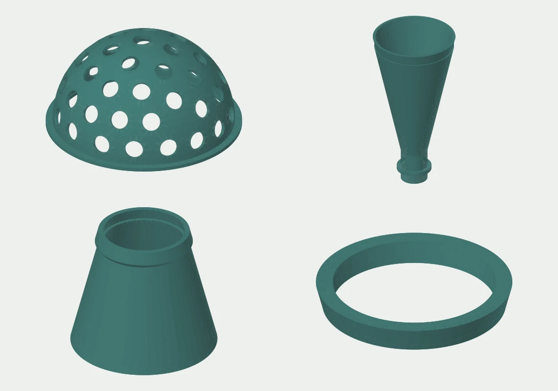
Retained Revision A horn sections, microphone retainer, core shell and joint coupons.
Download version ZIP 2.0 MB13 individual print & CAD files
- AH 001 assemblySTEP · 5.1 MB · CAD assembly reference
- AH 001 P01 rear hornSTL · 273 KB · Print geometry
- AH 001 P01 rear hornSTEP · 33 KB · Editable CAD
- AH 001 P02 front hornSTL · 160 KB · Print geometry
- AH 001 P04 core shellSTL · 1.3 MB · Print geometry
- AH 001 T01 joint maleSTL · 82 KB · Print geometry
- AH 001 P02 front hornSTEP · 18 KB · Editable CAD
- AH 001 P04 core shellSTEP · 875 KB · Editable CAD
- AH 001 T01 joint maleSTEP · 13 KB · Editable CAD
- AH 001 P03 mic retainerSTL · 62 KB · Print geometry
- AH 001 T02 joint femaleSTL · 82 KB · Print geometry
- AH 001 P03 mic retainerSTEP · 13 KB · Editable CAD
- AH 001 T02 joint femaleSTEP · 13 KB · Editable CAD